By 1925, radio was everywhere. Newspapers, churches, universities, and local businesses were rushing to set up broadcasting towers, and consumers for the first time could hear the world straight in their living rooms. It was also the height of the silent film era, proving moving pictures were the future. The question was obvious: if sound could be channeled through electricity, why not sight?
There were two major technical challenges that needed to be cracked for television:
- How to convert light into electricity
- How to deconstruct a moving image into a single transmissible signal
Both problems had been worked on before John Logie Baird entered the scene. Most of the science was there, but the engineering challenges had yet to be overcome.
The key discovery was the photoconductivity of selenium by English engineer Willoughby Smith, who had accidentally stumbled upon the property while testing underwater telegraph cables. He needed a high-resistance material to test his cables and he chose selenium. His test circuits worked perfectly in lab conditions, but in service it gave inconsistent results. He investigated, and found that selenium's resistance drops sharply when exposed to light. He had discovered photoconductivity
The reason lies in how electrons behave inside a solid. Their energies are restricted to certain allowed ranges called bands. Two matter here: the valence band, the highest band normally filled with the atoms' outer electrons, and the conduction band above it, normally empty. A filled valence band can't carry current—every electron is locked in place. To conduct, an electron has to be lifted across the gap into the empty conduction band, where it's free to roam. In selenium that gap is about 2 eV.
Photons of visible light carry about 1.6 to 3.1 eV, so selenium's band gap of 2 eV falls in the middle of the visible spectrum. This means a normal photon of visible light carries enough energy to throw an electron across the gap. The electron in the conduction band is then free to roam. If more photons arrive (i.e. the light is brighter), they lift electrons into the conduction band faster than the electrons can fall back. Selenium's resistance decreases as more electrons are freed to carry a current, exactly what Willoughby Smith noticed when laying his cables.
Each photon collision actually creates two charge carriers, not one: the freed electron and the positively charged hole it left behind. The hole moves opposite to the electrons, since each time a neighboring electron fills the gap, the hole shifts one step in the other direction, like the blank tile in a sliding puzzle.
Connect a battery, and its electric field pulls the electrons toward the positive terminal while the holes drift the opposite way, toward the negative one. Both motions carry current.
This solves the problem of converting light to electricity–use a selenium cell.
The first prerequisite was solved: selenium cells could convert light into electric signals. The second seemed more fundamental: how do you collapse a two-dimensional image, moving in time, into a one-dimensional signal, and then reconstruct it back again? Light isn’t like sound, there was too much information.
The obvious approach was to break the image up, send it piece by piece, and reconstruct it in sequence. This was called scanning.
There were limits: it had to be incredibly fast, so images could be sent quickly enough for the eye to perceive them as continuous, and the scanner had to stay synchronised with the receiver–both knowing which pixel went where. If they fell out of step, line by line and frame by frame, the picture would dissolve into noise.
Once the image was filtered through the disc, John Logie Baird added a selenium cell, which converted the rasterized light into a continuous signal.
In 1884, Paul Nipkow, a German student, patented a method of scanning using a spinning disc pierced with a spiral of evenly spaced small apertures (holes or lenses). As the disc spun, it swept across the image and broke it up into an array of lines, scanning one image per rotation. Because the disc was opaque, it means that at any instant, only light from a small section of the image is being displayed, converting a two dimensional image to a one dimensional signal. The scanning had to be repeated many times a second to create a moving image–the human eye starts to see smooth motion at about 30 frames per second, so discs had to rotate fast.
The holes sit on an Archimedean spiral so that the radius drops linearly with angle. Over one full revolution (2π) the radius must drop by exactly the picture height H, so the next hole starts scanning the line just below the previous one. N holes = N scan lines per frame. There were inherent physical limits here on the speed of the spinning disc and the resolution of the scanned area.
If I wanted a TV in 720p, with a picture half a meter wide each of the 720 holes has to sweep the full 0.5 m width during its slice of the rotation, and there are 720 of them crammed around one circle. So the circumference at the holes' mean radius must be at least N × W:
So for a normal size TV display, you would need a disc larger than a football field. At 30 frames per second, it would also need to spin.
That is many times faster than the speed of sound–nearly the top speed of Artemis II, so unfortunately your television will not be able to connect to your sound system.
Given the inherent limitations, mechanical television with spinning discs was never going to last. But none of the alternatives to disc scanning were feasible (most involved complicated mirrors), so Baird went ahead with the Nipkow disc.
To reconstruct an image scanned with a Nipkow disc, you use another disc, rotating at the same speed. There were two methods Baird tried for this. The first is shown on the right, using a copper brush with a current running through it as a rotary switch. The brush sat at the end of an arm and swept continuously around a ring of small contacts, one contact for each tiny lamp. As the brush rotated, it connected the incoming signal with the lamp in the corresponding scanned position, lighting it with a varying touch before moving on to the next. There were problems with this-it required lots of tiny lightbulbs and the contact pressure was unreliable. Baird later reduced the number of lightbulbs from N² for an N-line picture to N by having the lightbulbs spin, but he later abandonded the contact method entirely in favor of his more famous method, modulating one neon lamp directly with the signal
Unlike incandescent lightbulbs, neon lamps can respond to current changes fast, blinking on and off again rapidly with no sluggish lag. By connecting a neon lamp with the incoming signal and putting it behind a Nipkow disc, the light flickered through each hole and the eye reassembles it into a small picture.
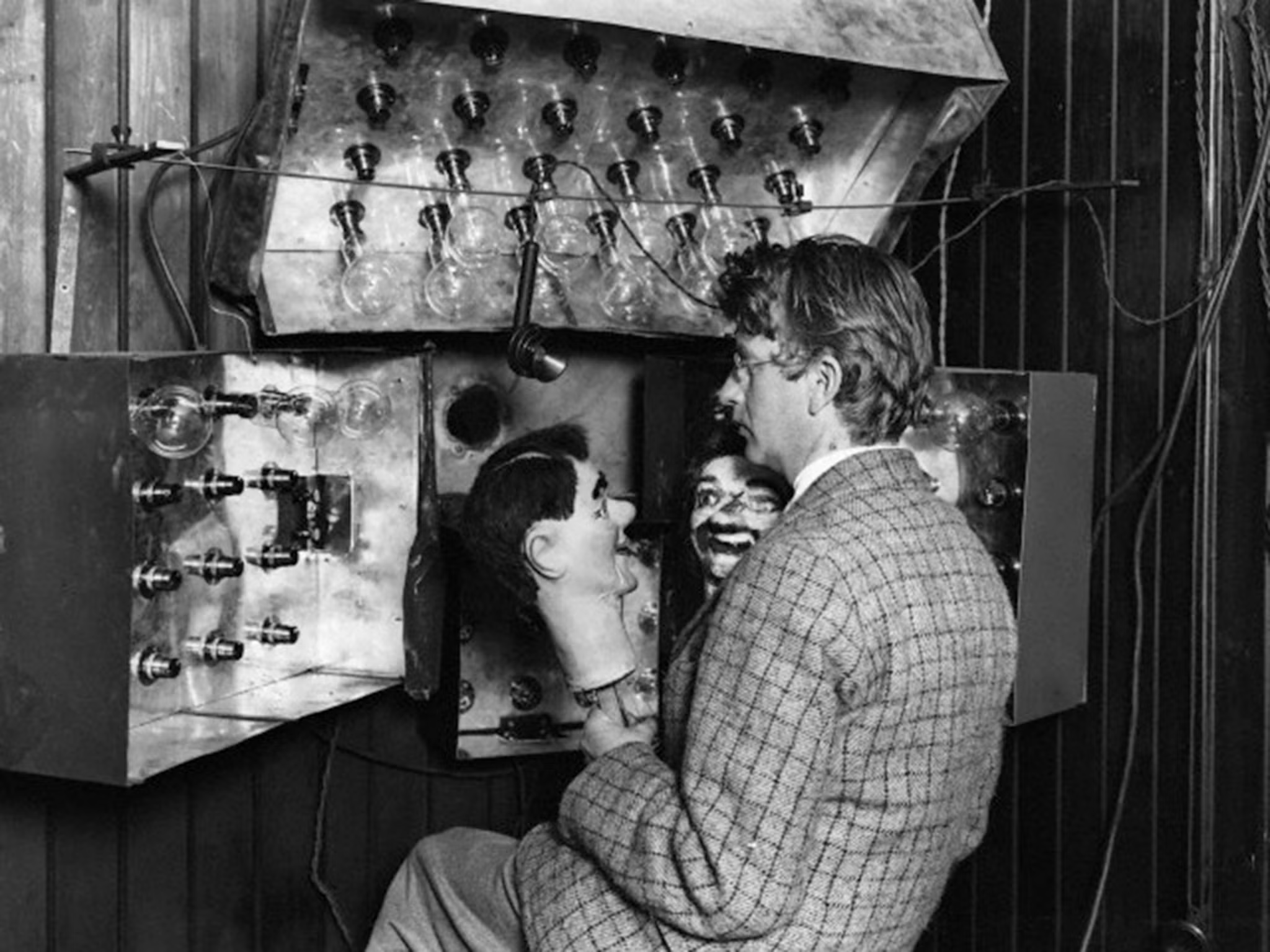
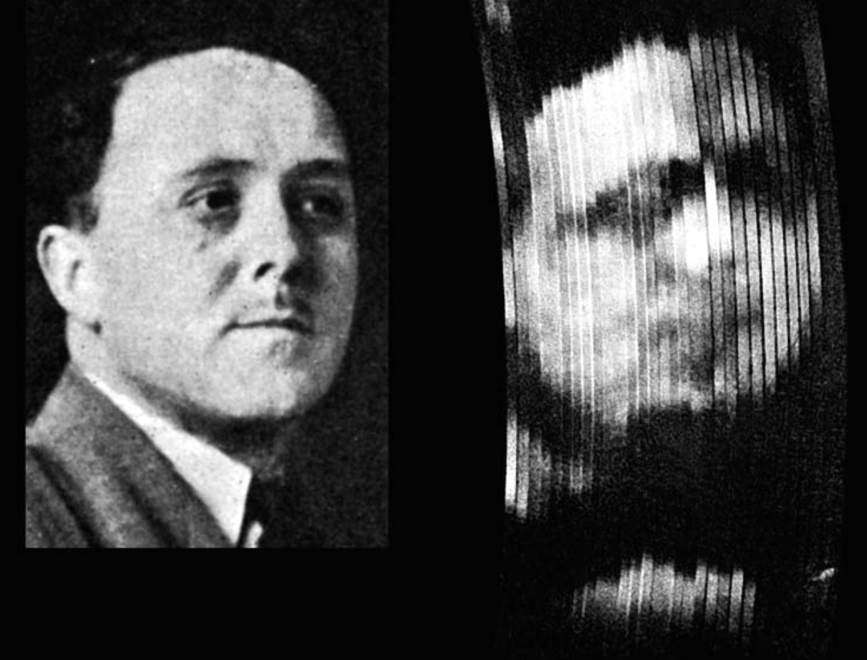
Using a hatbox, lenses from bicycle lights, a big wooden tea-chest, a coffin board from the local undertaker, sealing wax, and string, in his laboratory on 2 October 1925, Baird successfully transmitted the first recognizable television picture: the head of a ventriloquist's dummy nicknamed "Stooky Bill." He used a Nipkow disc with 32 scanning holes, rotating at five revolutions per second, and reconstructed the image with a neon lamp.
There were a few subtle problems to overcome. The first was selenium was… not great. Changes in light intensity did not cause instant changes in resistance, instead lagging slightly behind. Selenium cells also had a slow recovery time. Getting clear images was difficult.
Baird had noticed that the selenium had a first-order lag, where the rate of change of the output is proportional to the difference between the input and the output. If you added the derivative of the current to the current itself, you could reproduce the original light more closely.
Capacitors do this. A capacitor stores charge in proportion to the voltage across it: $$Q = CV$$ where Q is charge (coulombs), C is capacitance (farads), and V is voltage. Current is defined as the rate at which charge flows: $$I = \frac{dQ}{dt} = C\frac{dV}{dt}$$ So the current through a capacitor is proportional to the derivative of the voltage across it, not to the voltage itself.
"Now I decided to build a second amplifier, battery coupled but with one transformer coupled stage, so that one amplifier could give me the time/current curve, and the second the time/rate of change of current curve. I would then mix the two until the time lag was corrected."
The second issue with selenium was the fact that it reacted differently to spikes in light compared to constant light. It tended to droop.
Baird's solution to this was to add a chopper — another spinning disc, spinning even faster than the Nipkow disc. This cut the light up, giving selenium a chance to "reset." Like tapping an old barometer to keep the needle from sticking. It also had the additional benefit of converting the signal from a DC to an AC signal. AC signals were also more convenient to amplify with the technology of the time.
The last problem had to do with the synching of the discs. If either disc was slightly too fast or too slow, the picture dissolved into noise. They needed to match perfectly, even across long distances.
He did this by feeding two coils, a quarter-cycle out of step — sine and cosine. One set of coils created a field pulling horizontally, the other set vertically. The idea was that their combined pull created a rotating magnetic field.
When the left-right pair is pulling the hardest, the top-bottom pair is lowest, and a quarter phase later they swap. The arrow is the combined pull, which never grows or shrinks. It simply rotates. Connect the disc to a magnet chasing the field, and the rotating of the disc is tied directly to the frequency of the current.
Even with all this, mechanical television was still grainy and inconsistent. The lights were too bright and the spinning discs were too loud. Mechanical television was never going to work.
Citations
- R.W. Burns — Television: An International History of the Formative Years
- Russell W. Burns — John Logie Baird: Television Pioneer
- Donald F. McLean — The Achievement of Television: The Quality and Features of John Logie Baird's System in 1926
- Donald F. McLean — Restoring Baird's Image